This project was original conceived as a passing comment to Boldport on twitter when we hinted that someone should re-programm the P***off board to say “Ho Ho Ho”. For those thinking up x-mass projects. How about reprogramming @boldport P ...
There's more
This project was original conceived as a passing comment to Boldport on twitter when we hinted that someone should re-programm the P***off board to say “Ho Ho Ho”.
For those thinking up x-mass projects.
How about reprogramming @boldport Pi***ff ckub board to say #HoHOHo ?
It wasn’t until after @boldport published the schematice to the board that I realised that we can do more that just getting the board to say a few festive comments. We noticed that could possible drive a low current motor using the signal line for the IR detector. After it was just a mater of designing the mechanical parts to animate our Santa.
The project is based around Boldport P***off electronics which is based on luck resistorCat protetor. The plan was to keep keep any modification to the electronics and firmware to a minimum. Unfortunately, the firmware had to be alter to allow use to only move the motor on certain audio clips and to allow use to play two or more audio clip in a row between IR triggers.
The electronics is essential a simple audio player that uses IR detector to trigger a play event. The audio is store on the SD card using Lucky Resistor custom file system. My version of the firmware power the motor whenever an audio clip with the name stating with the letter ‘M‘ is played. It will also start playing a second audio clip if the first start with the letter ‘S‘. Plaing to clip in a row was important because there are some situation that I want Santa to say a few things without the motor moving. For example, Santa might say ‘Ho Ho Ho Merry christmas’ and then next play a song where the motor needs to move.
Here’s a video of testing Santa with the standard firmware and random song.
here’s video of the completed project
Project Resources and design files
Before I explain how the project was designed and build, I want to first list all of this project resources and design files. This should make it easier for anyone who is just looking to get access to the design files without having to read through the rest of the project documentation.
Sites
This are the links to site that were usefull through this project.
Luck Resistor P***off project – documentation for loading the SD card with the audio files and editing the firmware
Online Gear Generator – Useful site for exporting Gear design as SVG files.
SOX – Command line tool for converting audio files
Luck Resitor Micro Disk – Window/MAC tool for creating image for loading on to the SD card.
Repository
Santa – This is where all the design files, firmware and audio files can be found for this project.
Design breakdown
Ideally I wanted to make a Santa to move kind of realistic however what I had in mind would very much like have put this project completion date will passed Christmas day (2016!) which wouldn’t have been fun. So to keep things simple (and achievable), I settle with a mechanical design that has a single degree of freedom which allowed Santa’s belly to move vertically as a set rate.
Now I had to be honest, I didn’t bother inspecting the circuit schematic to see if there’s was anything already build into the design that would allow for any kind of motor to be controller. I actually started by picking out a geared dc motor from a selection that I already had in lab. if you think about it, counter intuitive considering that I wanted to keep the workload to a minimum and picking motor first doesn’t help. In fact, i was quite lucky that motor and electronics were a perfect match.
Motor
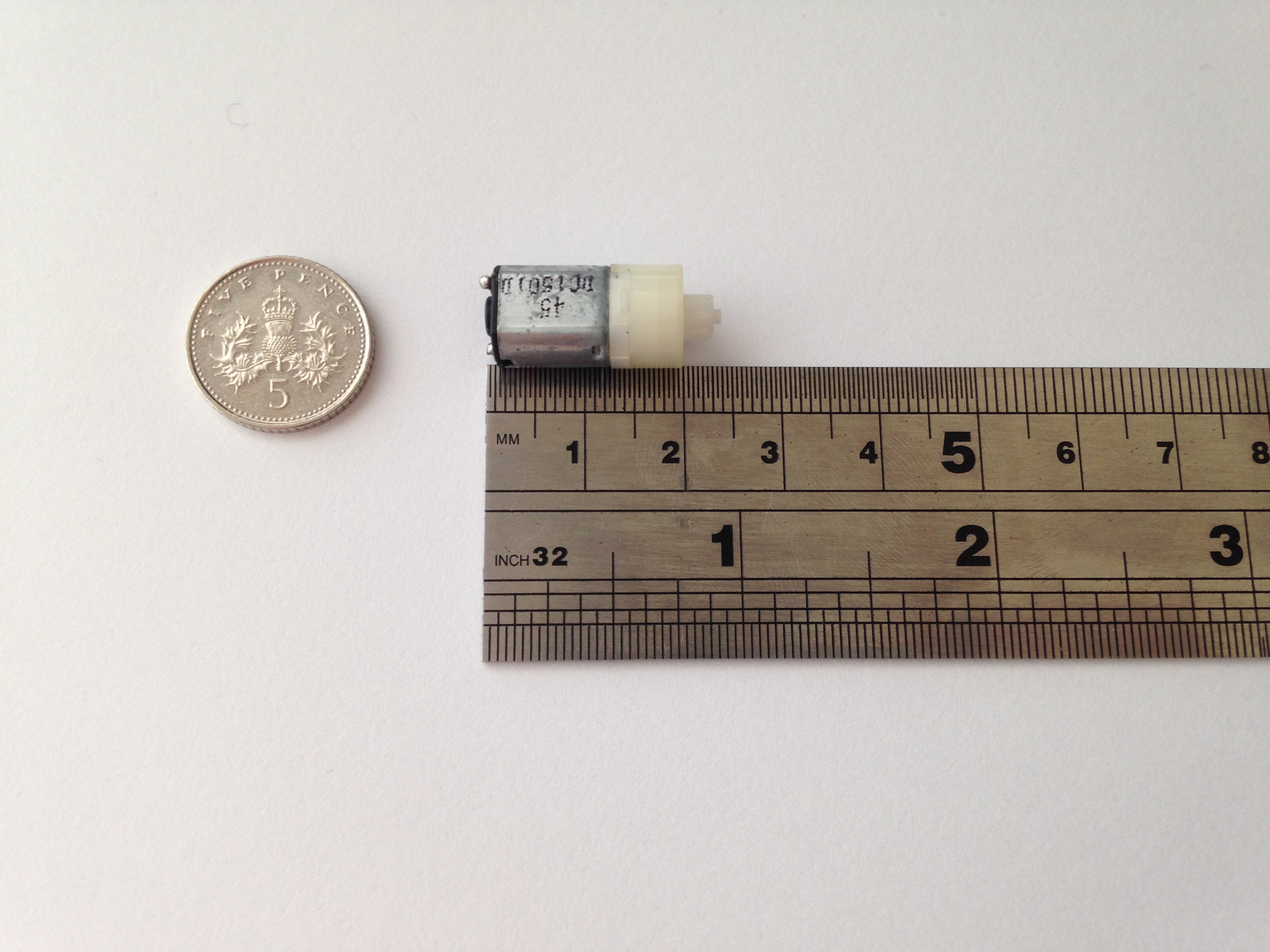
This is the motor that I chose to use. Its the 10GP-M10 which is 3v planetary geared motor that runs at 50RPM. The motor RPM rating will vary depending on who you are buying it from in aliexpress so beware if you are wanting to source this for a product.
I chose this motor because I have quite a few spare that were laying around from my micro robot project and I didn’t really want to spend any more time in waiting for parts to arrive.
I could have used a servo to animate Santa and in fact it would have simplified the mechanical part at the expense of extra code. Normally I would have opted to simplify the hardware over the code but considering that I already have to design and print part and all that I we have to do move part of our Santa back and forth at a set speed then really there that much more work on the mechanical side. Plus it nice for a change to keep the code simple because all we would have to do is control the motor on and directional state and if we do it right then the direction could also be eliminated.
This motor pulls around 100mA (~ish) on load and around 50mA unloaded. I’m not sure about stall or the current required to start the motor but I’m happy to assume something around 300mA.
Can the electronics handle our motor?
Yes it can.
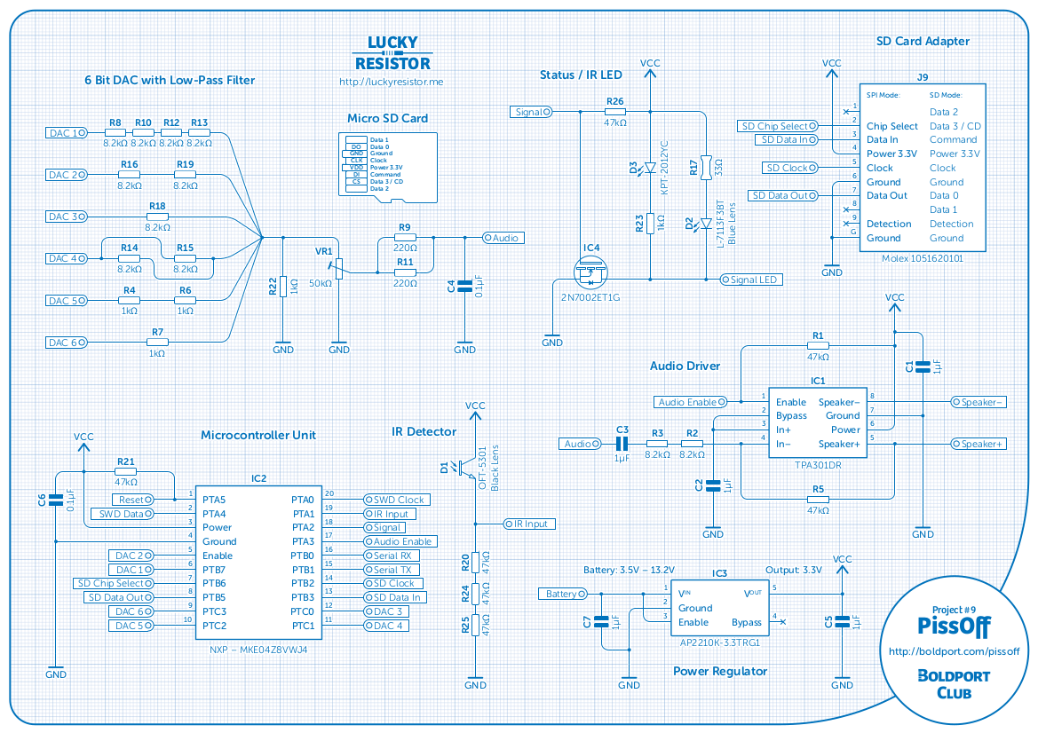
Turns out that the circuit has the IR and status LED pin signal routed out to a couple of connectors (see J10 and J2) which makes triggering to this signal easy. What’s nice about this signal is that its driving my a mosfet (see IC4) in a open collector configuration. The MOSFET used is the 2N7002E which can handle at least 400mA when the gate voltage is at 3.3V. This is more than enough to start and drive our motor.
Firmware changes
The issue with using this signal line to drive the motor is that is shared with the IR emitter which pulsed when its in detection mode. Now this isn’t too bad because during the detection mode the signal isn’t on long enough to provide sufficient power to cause the motor to move. Not a problem but it kind of remove the chance of our Santa monitoring the IR while its moving its belly which could of been handing for other type of interactions.
Now a bigger issue I had to sort out with the firmware is that toggle the IR emitter signal at the audio sample rate when its playing a tune (44.1khz). This is because emitter is also shared with a status led which is handy when you first set it up. However, 44.1khz signal wasn’t enough to keep the motor moving at a reasonable rate so this bit of the code was changed.
So now, the firmware will keep the IR emitter signal high when certain files are played and keep off of others and It still toggle signal when in detection mode.
Mechanical design
I end up using a crank mechanism for converting rotational to linear movement. The nice thing about it is that the motor only needs to rotate in one direction to provide the up and down motion that we need.
To be honest, the rate that the belly moved at was lossly based on what I though would make our Satan seem like its having a good chuckle. So guesstimated that the belly would move up and down at a rate of twice per second. i don’t mind it going faster because I figured I could always reduce the motor speed mechanically or by software.
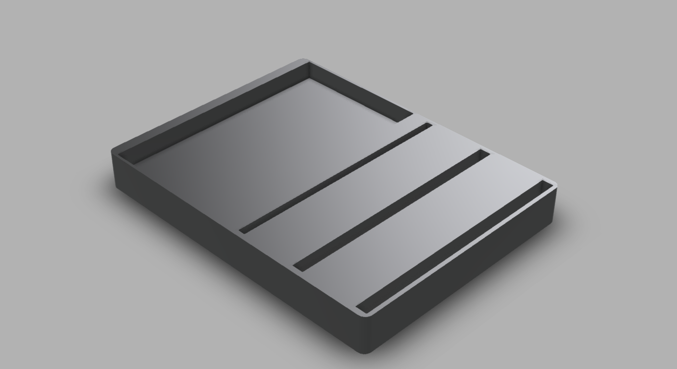
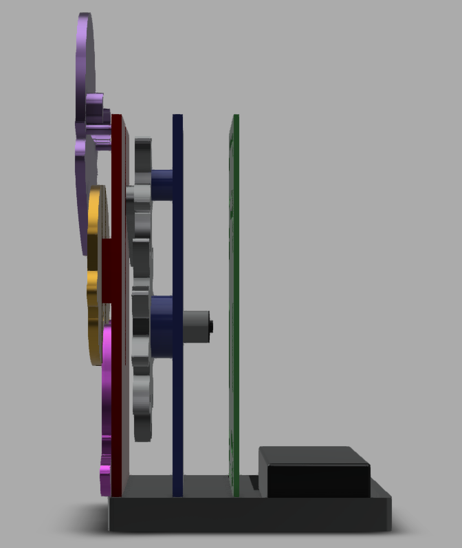
The only mechanical design constrain that I had was to try and keep Santa overall size close to the electronics PCB footprint. I also end up sandwiching all the mechanical parts together by slotting them all in into base. this is the one I ended making.
The large space at the back is where the battery holder is place where the smaller slop is for the PCB. the other is to hold the gear holder plate and the final slot on the front is for the pate that holds the decoration belly guiding rails.
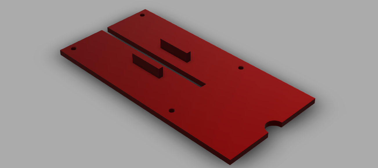
This is the plate that holds the decoration and has the guiding rails for the belly
This is the plate that holds the gears and motor in place.
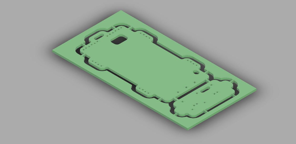
This is the CAD model for the PCB
This is with the gear and motor mounted.
This is all the part in place.
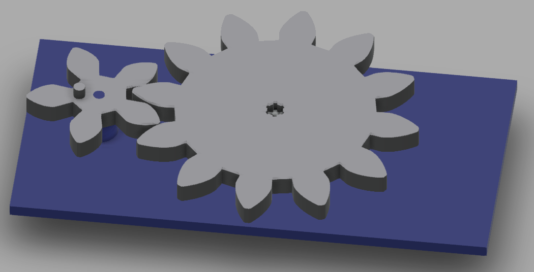
Gears
So with that in mind, I needed to step up the speed of the motor some gear configuration that would allow give me something close to 2s. I also need to design the gears but I didn’t facing spending too much time printing various gears configuration and design so I figure I try using a gear generator.
Unfortunately, Fusion 360 doesn’t have a easy to use or free gear generator but I did how ever find an online generator that expert to SVG which fusion can use to import. The generator only create 2D design but the rest I can do myself.
The only tool I used it geargenerator.com. You simple type in your required parameters and it does the rest. When you are happy can then import the output into fusion 360 as a drawing that you can use to extrude. So the gear were sorted.
Sensor placement and why model the PCB
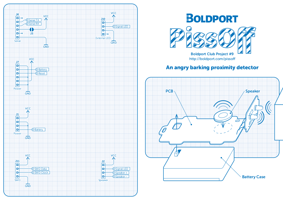
The handy part of the electronics is that you have the choice where to mount the sensor. Now sensor part is meant to look some a person head and by design its meant to be cut of its frame and place where you want it. For this reason, I made sure that Santa proportion matched so that the sensor would act as Santa’s eyes.
So to achieve this, I imported the electronics design files which where generated with inkscape (thank you Saar for @pcbmode) as SVG into fusion 360. it was a easy as telling fusion 360 to extrude the PCB outline by 1.6mm.
I also when ahead and create a model of just the head portion of the PCB so that I can check the Santa’s eye position.
Drawing Santa and creating the model
Santa was design to be made out of three parts. The head, body and legs. The head which requires a method to holds the sensor in place, the body which needs to have enough space to allow for whatever method I chose to connect it to the crank and the leg just need to be long enough hide the empty space behind the body.
I used inkscape to create the Santa design. I first imported the PCB outline so that I know where and what proportion to make Santa.
This is what I came up with.
I them took the outline of each parts and import it into fusion 360 where I then created the models.
More to come!
Sorry there’s still more to write. Unfortunately it will have to wait until After the new year where I will be finishing off the write up and publish the recordings that I made of designing and making the Santa.
Leave a comment.
Please note that all comments are moderated by a person and so it may take some time for it to show on the site.
if you have an urgent issue then please feel free send us a message via our contact form below.
Whether you have an existing project that you need help with or if you want us to take care of the whole design process, we are happy to talk to you about your project and see if we can help. At the very least we should be able to point you in the right direction.


Leave a Reply